
|
|
|
ABSTRACT An investigation of direct solar-thermal hydrogen and oxygen production from water is described. Nozzle jets and skimmers have been used for separation of the products and suppression of recombination. The dissociation of water vapor and the separation of its products was conducted in plasma-enhanced, non-equilibrium glow discharges. In this report we describe the status of our work with a solar water dissociation gas phase reactor: Solar radiant energy was concentrated by a parabolic mirror to produce high temperatures on a nozzle inside a solar reactor fed with water vapor (steam) at low pressure, to produce hydrogen and oxygen.
INTRODUCTION A sustainable, non-polluting energy currency is required to provide for human needs such as cooking, heating, transportation, electricity production, and refrigeration. An economically viable method for producing large quantities of hydrogen from water using sun-light would satisfy this need, in a "Hydrogen Economy". Pioneering studies of solar hydrogen and oxygen production from water occurred throughout the world during the 1970's and early 1980's as a response to the oil shocks of 1973 and 1978/1979. After a lull in activities during the mid and late 1980's, interest in direct water dissociation and other hydrogen production technologies has again increased during the early 1990's due to increasing environmental problems. WATER DISSOCIATION TO PRODUCE HYDROGEN AND OXYGEN Our research objective is to develop a process that can attain a high level of water vapor dissociation and efficiently separate the hydrogen from the oxygen and un-converted water vapor. At high temperatures, above about 1800 K, water vapor (steam) begins to dissociate into a mixture of H2, O2, H2O, O, H and OH. The extent of dissociation increases with increasing temperature and decreasing pressure. The water and the diatomic hydrogen and oxygen species completely dissociate into H(atomic hydrogen) and O (atomic oxygen) above about 3500 K under equilibrium conditions at 1 mm Hg absolute pressure. ENDOTHERMIC WATER VAPOR DISSOCIATION REACTIONS Endothermic reactions can be carried out with the aid of electricity, as in electrolysis. However, thermal power from concentrated solar radiation can be used without any mechanical or electrical input and without the aid of any catalyst to achieve water dissociation. The direct thermal method has two advantages: it is very simple in its principle and it is versatile and adaptable to many endothermic gas-phase reactions. This method does not suffer from the corrosive reagent problems of various multi-step lower temperature thermo-chemical cycles. New problems arise, however, in finding reactor materials capable of withstanding the higher temperatures required with one-step concentrated radiation water-thermolysis. The materials used in the reactor must be capable of withstanding the thermal cycling and shock brought about by the intermittent nature of solar diurnal and weather cycles. The chemical reactions associated with high temperature dissociation of water vapor are shown below, along with their pressure equilibrium constants:
Where P is the total pressure and X is the mole fraction. Equation (1) above is an over-simplification of the primary reaction, because surface reactions in this reactor are significant. The surface reactions have been well characterized by Lede et al 1982). Water vapor dissociation has an activation energy threshold of about 135 kcal/mole (5.9 electron volts). Atomic hydrogen and oxygen are formed and then recombined to diatomic hydrogen and oxygen, losing about 78 kcal/mole in the recombination process. In this investigation we are studying the non-isothermal low-pressure glow-discharge region shown in Figure 1 (Bockris et al, 1985). It can be seen that the enthalpy change may be greater than the water dissociation activation threshold of 135 kCal/mole(5.9ev). 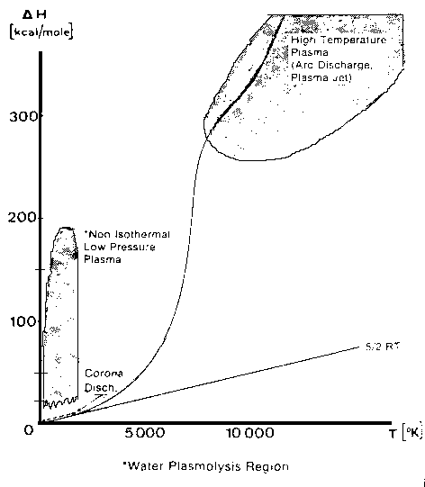 Glow Discharge Region Between Feed Ring and Nozzle NON-EQUILIBRIUM PLASMA-CHEMICAL REACTIONS ASSOCIATED WITH WATER VAPOR GLOW DISCHARGES The process of decomposition of water in the plasma state can be accomplished at highest efficiency where the electron temperature is not sufficient for intense excitation of the electron states, and the larger portion of the electron's energy contributed to the discharge is expended for excitation of vibration modes and for dissociative attachment (Melik-Asloanova et al, 1978). The total efficiency of the process depends on the energy losses in the discharge, the efficiency associated with the negative contribution of the chain-breaking reaction, the heat losses of the excited-state reactions, and finally on the efficiency of the reaction relative to the oscillative relaxation. The energy transfer efficiency of vibrational excitation by electron impact is a function of the energy contribution to water: oscillations, translational motion, rotation, and dissociative attachment. The energy transfer efficiency of the chain process depends on the chain length. DISSOCIATOR-NOZZLE APPLICATION TO PRODUCTION OF HYDROGEN AND OXYGEN FROM WATER VAPOR A block diagram of the Photo-separatory Nozzle reactor (Pyle 1983) and the process under investigation is shown in Figure 2: 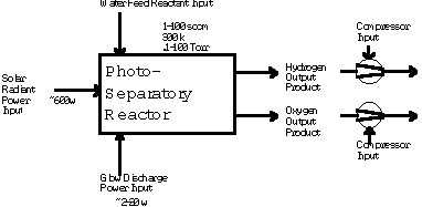 Block Diagram of Solar Reactor CONCENTRATION AND ABSORPTION OF SUNLIGHT IN SOLAR REACTOR Sun-light was concentrated using a parabolic mirror and directed through the entrance window of a high-temperature gas-phase reactor. Inside the solar reactor the concentrated radiant energy was focused onto a trumpet-shaped ceramic dissociator-nozzle. An optical pyrometer with a video camera looks through a prism and a hole in the concentrator mirror, then through the quartz reactor window to view the dissociator-nozzle surface and obtain nozzle surface temperatures. The solar spectrum,at sea level on Earth with air mass of 1, loses some energy bands due to the water vapor absorption which occurs as the light is passing through the atmosphere, especially in the near UV. This absorption limits the energy spectrum available for water dissociation at the earth’s surface. We used re-radiation from a hot surface (the nozzle) to enhance gas heat transfer and create a surface reaction site. Solar heat source temperature can be calculated as a function of the concentrator optical concentration ratio, reflection coefficient, and arriving solar power density. By raising the temperature of the nozzle surface to a sufficiently high value (using the nozzle as a target for concentrated sunlight) and dropping the water vapor pressure to a sufficiently low value, we are attempting to produce significant water vapor dissociation. GLOW-DISCHARGE ENHANCEMENT OF RADIATION AND CONVECTION HEAT TRANSFER AT NOZZLE ENTRANCE A high voltage DC electric power supply (PS-1) was used in some of the experiments to create a water-vapor glow-discharge between the water vapor feed-ring and the entrance to the ceramic dissociator-nozzle to enhance dissociation (Pyle et al, 1994). See Figure 3. 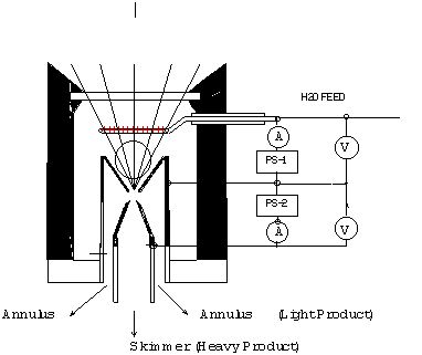 Photo-separatory Nozzle Reactor The applied voltage was measured with volt-meter V and the current with ammeter A, shown in the upper right of Figure 3. The circle shown in Figure 3, between the feed ring and the dissociator-nozzle, is where the solar image "fireball" and the water vapor glow-discharge region are located. The partially dissociated water vapor was allowed to pass through the dissociator-nozzle throat and expand into a lower pressure region. The pressure inside the dissociator-nozzle tube (downstream) must be lower than at the entrance (dissociation region) to create the driving force for sonic flow through the nozzle throat (pressure ratio > 0.55) , and produce a jet and shock-wave down stream. In our application a sonic dissociator-nozzle geometry was used because this was the easiest to fabricate using quartz tubing in the laboratory. All gases at room temperature are excellent electrical insulators. In order to make them electrically conducting, a sufficient number of charge carriers have to be generated. If a sufficiently high electrical field is applied to a pair of electrodes separated by a volume of the gas, an electrical breakdown of the originally non-conducting gas establishes a conducting path through the electrode gap, producing an array of phenomena known as gaseous discharges. We desire a steady-state dc glow discharge for our solar plasma reactor, to obtain a higher electron population density with relatively low electrical power consumption. After breakdown, the current A rises and voltage V drops to steady-state values. The discharge voltage depends on the current and certain properties of the discharge tube, such as gas type, gas pressure, electrode material, and electrode temperature. A current suppression (or ballast) resistor is needed to limit the current through the gas-plasma after breakdown occurs. We used 10,000 to 18,000 ohm suppression resistors in the Photo-separatory Nozzle reactor. Heat is supplied to the dissociator-nozzle (which is also the cathode electrode for the glow discharge) by the concentrated solar beam, and it operates in glow discharge with low cathode fall. Cooling of the nozzle surface by electron boil-off occurs under direct thermionic emission process conditions at very high temperatures. Indirect emission processes (secondary emission processes) are also important to consider: electrons are ejected from the surface of the nozzle by energetic particles such as ions and photons in the glow discharge. GLOW DISCHARGE APPLIED BETWEEN DISSOCIATOR-NOZZLE AND SKIMMER SEPARATOR A supersonic beam skimmer was installed behind the shock wave to separate hydrogen and oxygen from the partially dissociated water vapor (Becker et al 1955). See Figure 3. The supersonic beam skimmer used was a knife-edged cone. The skimmer was positioned with micrometers so that its entrance was at the down-stream edge of the shock-wave envelope produced inside the dissociator -nozzle. An appropriate pressure ratio was applied between the low pressure dissociator-nozzle jet region and the beam skimmer interior to improve the separation factor for hydrogen and oxygen production. This jet separator functions by transverse gas diffusion. The hydrogen and oxygen (plus unconverted water vapor) are separated because the hydrogen gas diffuses transversely (relative to the jet flow axis, more rapidly than oxygen or water), due to its lower mass. A second high voltage DC electric power supply (PS-2) was used to create a glow discharge between the sonic dissociator-nozzle and the conical skimmer nozzle to study separation enhancement by cataphoresis. Cataphoresis is the spatial gas density gradient which forms near a cathode within a glow discharge. Cataphoretic efficiency has been observed to decrease with increasing temperature, however. The glow-discharge between the dissociator-nozzle and the skimmer-nozzle also allows shock-wave visualization by a video camera which is aimed through a viewing slit in the reactor wall. The video camera is attached to a coherent optical fiber bundle and illuminated with a He-Ne laser through another incoherent optical fiber bundle to allow observation of the dissociator-nozzle and skimmer separation distance, as the skimmer is moved in or out of the jet. Enrichment of heavier-mass species occurs in the core of the gas jet. Enrichment of the lighter-mass species occurs in the periphery of the gas jet. The free molecular diffusion separation arises from the disparity in the thermal velocity of light and heavy gas molecules, for gases with the same mass flow velocity and local temperature. The heavier species have a lower thermal velocity and expand less (laterally) after the transition plane, remaining more concentrated at the beam center. In moving the skimmer transversely a qualitative measurement of the degree of beam spreading is obtained. A much broader spreading is observed for light species (hydrogen) than for heavy species. In the case of a fixed skimmer-orifice dimension, an axially movable skimmer is necessary to achieve comparable beam intensities for different gases. The mass separation factor is approximately proportional to the mass ratio when the skimmer-interference and background-penetration effects are minimized. Separation Factor = [(Heavy Core Gas, M%) (Light Peripheral Gas, M%)] / [(Heavy Peripheral Gas, M%) (Light Core Gas, M%)] GLOW DISCHARGE POWER SUPPLY REQUIREMENTS In the dark (no concentrated sunlight), with water vapor pressures in the Photo-separatory Nozzle reactor's normal pressure regime, the power supply voltage required for sustaining normal glow may be about 700, whereas under concentrated sun-beam illumination the normal glow voltage is only about 200. The current requirement is on the order of 1-3 ma under either dark or illuminated conditions. The use of higher pressure requires the use of higher current. The glow-discharge power is only a small fraction of the power arriving via the concentrated sun-beam, about 1 to 2 watts typically. This electrical power requirement can easily be met by a small photovoltaic cell array. The glow-discharge power for the lower pressure gas region between the dissociator-nozzle and the skimmer is of the same order as for the feed-ring to dissociator-nozzle power, 1 to 2 watts. DESCRIPTION OF EXPERIMENTAL APPARATUS 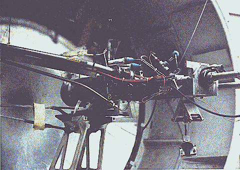 Photo-separatory Nozzle reactor A computer program, called Iontrack, calculates the elevation and azimuth of the sun based on the time of day, and the latitude and longitude of the mirror on the planet's surface. Iontrack reads the actual elevation and azimuth positions of the mirror from the two analog sensors, and determines the movement required for each axis to reduce the error to zero. Iontrack directs the two stepper motors to make the necessary movements to keep the tracking error under 0.10 degrees. PHOTO-SEPARATORY NOZZLE REACTOR CONSTRUCTION The Photo-separatory Nozzle reactor was constructed from concentric quartz tubes and surrounded by a convection and conduction barrier with radiant energy reflecting properties. See Figure 5. 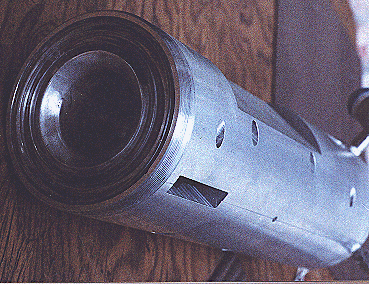 Reactor Containment Vessel An aluminum housing protects the quartz tubes, aligns and holds the silicone "O" ring seals in place, and serves as a mounting fixture on the stage of the searchlight concentrator. An optical viewing slit in the reactor containment vessel was provided for studying the transonic flow region, between the dissociator-nozzle and the skimmer. 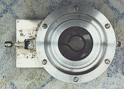 Figure 6 Solar Beam Entrance Window with Feed-Ring GAS (WATER VAPOR) FEED-RING ELECTRODE The feed-ring electrode was made from a loop of stainless steel tubing. The tubing was welded closed at one end and drilled with feed holes 0.508 mm(0.020 inches) diameter chamfered 1 mm (0.040 inches) periodically at 1.27 cm (0.5 inch) intervals along its length. The tubing was then rolled around a mandrel to form the feed-ring electrode. A quartz tubing sleeve was used as a feed-through insulator at the reactor window retainer wall to supply reactant gas and electrical power. The electrical power supply connection to the feed-ring electrode is made outside the reactor on the stainless steel gas feed tube. It is important to operate the reactor when it is "on-sun" with water vapor flowing to the feed ring. In one experiment water vapor feed was interrupted and the stainless steel feed-ring was evaporated. The feed-ring turns black after operation on-sun for a few hours, but is not damaged by the beam as long as the water vapor feed is continuous. SONIC DISSOCIATOR-NOZZLE/ELECTRODE FABRICATION The dissociator-nozzle is a sonic nozzle with a trumpet-shaped converging entrance section made from a cylindrical quartz tube. A sealing flat flange was fused to the opposite end of the tube. A conductive thin film of platinum was applied to the outside of the quartz cylinder to provide an electrical connection (negative ground) for the dissociator-nozzle. The quartz tubing (General Electric Type 204 clear fused quartz) was coated with an yttria and calcia stabilized zirconium oxide refractory (Aremco Products Inc. Ultratemp 516 high temperature ceramic adhesive, Osining, New York) for the reaction zone and solar beam target. The sonic quartz dissociator-nozzle is shown in Figure 7. 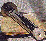 Sonic Quartz Dissociator-Nozzle with Ceramic Zirconia Coating After 10 to 20 hours of on-sun operation, samples of a broken zirconia-on-quartz dissociator-nozzle were analyzed by x-ray diffraction. Zircon (zirconium-silicon oxide) micro crystals were detected, indicating a new conductive interface layer had been formed between the quartz tube and zirconia coating. Better thermal-expansion matching of materials seems to be obtained with a zircon layer. A glassy surface finish is produced on the heat-affected portion of the dissociator-nozzle coating after "break-in". SKIMMER NOZZLE/ELECTRODE The skimmer nozzle/electrode is a conical nozzle that is mounted on the end of a cylindrical stainless steel tube which fits coaxially inside the cylindrical dissociator-nozzle tube. See Figure 8. The conical skimmer-nozzle/electrode entrance faces the dissociator-nozzle's exhaust jet. The conical skimmer-nozzle was fabricated from a sharp-edge truncated cone made of quartz tubing and ground to a knife-edge using a diamond abrasive wheel. The quartz skimmer-nozzle was coated with platinum for electrical conductivity and connected (via a feed-through) to an electrical power supply (PS-2 in Figure 3) on the outside of the reactor.  Conical Skimmer Nozzle/Electrode PRODUCT SEPARATION CONTROL SYSTEM A scissors jack is used to move the skimmer in and out with respect to the dissociator-nozzle exhaust axis. The scissors jack counteracts the forces on the skimmer caused by atmospheric pressure exerted on one side of the skimmer and the lower process pressure on the inside of the skimmer. An electronic proximity sensor and a dial gauge are used to provide axial position information. The spacing between the dissociator-nozzle and skimmer is of the order of one nozzle diameter (about 1mm.) The skimmer can be moved from about 0.1mm to about 2.0mm downstream of the dissociator-nozzle. Depending on the pressure in the region between the dissociator-nozzle and the skimmer this distance is approximately 1 mean-free-path (between atom/molecular collisions). An eccentric is used to move the skimmer from right/left and up/down around its pivot point. The pivot point is located about 22 cm downstream from the dissociator-nozzle’s exit orifice. The pivot point is made from 3 dimples inside the dissociator-nozzle tube. Two more proximity detectors and dial gauges provide up/down and right /left skimmer position information. Sampling valves are located in the two product discharge lines. Each sampling valve can admit product gas into the mass spectrometer. The spectra from each product line are alternately taken; then the mass spectrometer background gas pressure spectrum is subtracted from each. The mass ratios for the light and heavy products are calculated and used to obtain a separation factor. The mass-flow rates of the water vapor feed and the skimmer (heavy product) and annulus (light product) were measured with Teledyne Hastings-Raydist model ST and model HFM-200H mass flow meters. Using the three mass-flow meters allowed us to perform a mass balance across the reactor to obtain measurement closure with the flow meters (as a calibration and leak check.) OPTICAL PYROMETER FOR NOZZLE SURFACE TEMPERATURE MEASUREMENT A Pyro Micro-Optical Pyrometer made by the Pyrometer Instrument Company Inc. (Northvale N.J.) was used to measure the temperature of the dissociator-nozzle surface under different operating conditions. We used an EC-6 high temperature range filter and a 90 degree M-14 prism to view the dissociator-nozzle. Corrections to the indicated temperature were made for the prism, the filter, the range selection, and the reactor window transmission loss for any given temperature. We normally measure temperatures in the 2300 K to 2800 K range at the nozzle surface, depending on the water vapor feed pressure and the solar beam flux. Stagnation temperatures as high as 3250 K have been measured on the nozzle surface (somewhat higher than the published melting point of zirconia.) Pumping the products from low pressure to atmospheric pressure or higher requires compression work, which is a parasitic loss in the overall efficiency of the process. The losses for the oxygen-rich stream compressor and the hydrogen-rich stream compressor must be minimized by selecting reactor pressures no lower than necessary, and by the use of efficient compressor designs. The net power required to pump the process fluids in this reactor was about 18 watts. To compress the products adiabatically (no cooling) from 1 Torr to one atmosphere with an inlet temperature of 300 K would require about 50 kJ/g-mole (11.9 kcal/g-mole). Isothermal compression (with intercooling) would require only about 1/3 as much compression work. An energy diagram which gives estimates for the losses in the process, both to the surroundings, and to parasitic power requirements is shown in Figure 9.
Figure 9 The optical losses can be reduced through:
The pumping losses and glow-discharge losses are, in reality, electrical power requirements, which, if met by photo-voltaic means, can be considered a capital cost. EXPERIMENTAL SEPARATION EFFICIENCIES AND SOLAR-TO-HYDROGEN EFFICIENCIES TO DATE Experimental solar-to-hydrogen efficiencies to date are shown in Figure 10. 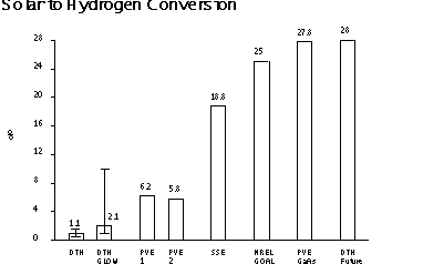 Efficiency of Solar-Hydrogen Processes The first bar on the left(labeled DTH) is the direct thermal hydrogen conversion efficiency obtained by analyzing the dissociator-nozzle jet flow-field without the use of a glow discharge or skimmer. About 1.1% solar-to-hydrogen (higher heating value) conversion was obtained. The second bar (labeled DTH Glow) shows an improvement in solar to hydrogen conversion to about 2.1% when a glow discharge was applied and the skimmer and annulus hydrogen production was added together. The maximum and minimum measured values are shown about the mean. The third bar (labeled PVE1) shows the solar-to-hydrogen
efficiency obtained using silicon photovoltaic cells and an alkaline
electrolyzer. The fourth bar (labeled PVE2) shows the results
of another photovoltaic electrolysis system. The conversion efficiency for a solar dish Stirling generator combined with an alkaline electrolyzer [75% efficient] is labeled SSE in Figure 10. The next bar (labeled NREL Goal) shows the long term solar-to-hydrogen efficiency goal established by the National Renewable Energy Laboratory, for reference purposes. Multi-junction single crystal gallium arsenide solar cells with future 37% solar-to-electrical efficiency combined with a 75% efficient alkaline electrolyzer is labeled PVE Ga As. The bar (labeled DTH Future) indicates that the future direct thermal hydrogen process may compete with other known methods on an efficiency basis. It may have the further advantage that it does not use expensive single crystal materials. MICRO-NOZZLE ARRAYS AND SCALE-UP Micro-nozzle arrays may allow scale-up of the process for a wide area solar reactor receiver. With smaller nozzles themean-free-path dimensions will also be smaller, and higher operating pressures will be allowable in principle. The higher operating pressure will result in a reduction of parasitic compression work required . The arrays can be arranged in matrices or linearly. We can envision arrays of solar-hydrogen reactors along two parallel pipe lines, running from an area with high insolation, to supply cities. Existing natural gas pipelines could be used to transport the hydrogen and oxygen products separately to their point of use. Alternatively, one pipeline could be used to transport hydrogen to the point of use and the oxygen could be vented. RECOMMENDATIONS FOR FUTURE RESEARCH AND EXPERIMENTATION We have seen that some direct thermal hydrogen production can be obtained in this reactor simply by passing water vapor through a hot ceramic nozzle (1.1%). We have also found that impressing a glow-discharge across the dissociator-nozzle almost doubles the conversion (2.1%). The separation factor for the skimmer has not yet been optimized. More work remains to obtain accurate spatial calibration of the skimmer, and investigate the effect of pressure, flow separation, and glow discharge on the separation efficiency. At this time the amount of recombination which occurs after dissociation is unknown. However, we feel there are very exciting possibilities for improvement of the process. Further improvements in product gas analysis (mass spectrometer)calibration and skimmer nozzle position calibration are needed to remove uncertainty from the measurements and provide real-time data during "on-sun" experimental runs. ACKNOWLEDGMENTS We are gratefull for the suggestion by John Green to consider the separatory-nozzle, as applied in mass-spectroscopy, to the separation of dissociated water-vapor in a solar reactor. We thank J.D. Healy, E.C. Petersen, and R. Cortez for their assistance in constructing and trouble-shooting the apparatus for these experiments. REFERENCES Becker, E.W. et al, 1955, "The Separatory Nozzle a New Device for Separation of Gases and Isotopes", Z. Naturforschg, Part A, Vol.10a, pp565-572. Bockris, J.O.M. et al, 1985, "On the Splitting of Water", International Journal of Hydrogen Energy, Vol. 10 No. 30, pp.179-201 Lede, J., Lapique, F., Villermaux, J., Cales, B., Baumard, J.F., and Anthony, A.M., 1982, "Production of Hydrogen by Direct Thermal Decomposition of Water, Preliminary Investigation", International Journal of Hydrogen Energy, Vol.7, No.12, pp.939-950. Melik-Asloanova, T.A., Abbosov, A.S., Shilnikov,V.I., 1978, "Dissociation of Water Vapor in Supersonic Flow of Non-equilibrium Plasma", Proceedings World Hydrogen Energy Conference 2, pp.1063-1069. Pyle, W.R., 1983, "Photo-separatory Nozzle", U.S. Patent No.4,405,594. Pyle, W.R., Hayes, M.H., Healy,
J.D., Petersen, E.C., Spivak, A.L., Cortez, R., 1994"Direct-Thermal
Solar Hydrogen Production from Water Using Nozzles/Skimmers and
Glow Discharge in the Gas Phase at Low Pressure and High Temperature", H-Ion Solar Company, NREL Task
No. HY413801, Subcontract No. AAP-4-14240-01, Richmond, California,
pp.1-63. |